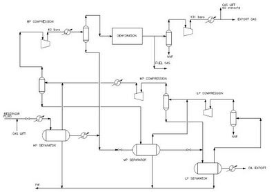
The typical process flow diagram (PFD) of oil and gas processing for most of fixed or floating offshore production. Two sections consists crude oil stabilisation and associated gas compression.
This section is continue to discuss the gas processing part in offshore production platform. The HP-MP-LP Separators separate gas from oil. The gas from LP and MP Separators will be recompressed by small compressor driven by electric motor. The re-compressed gas co-mingle with the gas from HP Separator. The gas send to HP Compression train for sale gas, gas lift or gas injection.
The HP Compression train included gas scrubber, gas cooler, anti-surge recycle and driver (gas turbine, steam turbine or electric motor). The gas compressed to higher pressure via several stages of compressors. Each compressor is driven by same shaft. Number of stage compressor is depended on final discharge pressure and compression ratio of compressor. The common compression ratio is maximum 4.
The imperial practice is equal compression ratio of each stage HP Compressor due to high efficiency and cost effective.
The gas treatment system allocate at interstage HP compression train. They are Gas Dehydration, Mercury Removal, Gas Sweetening, Hydrocarbon Dew-point Control Unit, or Natural Gas Liquid Recovery Unit. The gas treatment system depend on gas export requirements.
The treated gas is exported via gas flowline or LNG/CNG tanker to onshore processing plant.

Figure 2: Floating Oil and Gas Production
You may interest:


No comments:
Post a Comment